Components illustrating design for manufacturing
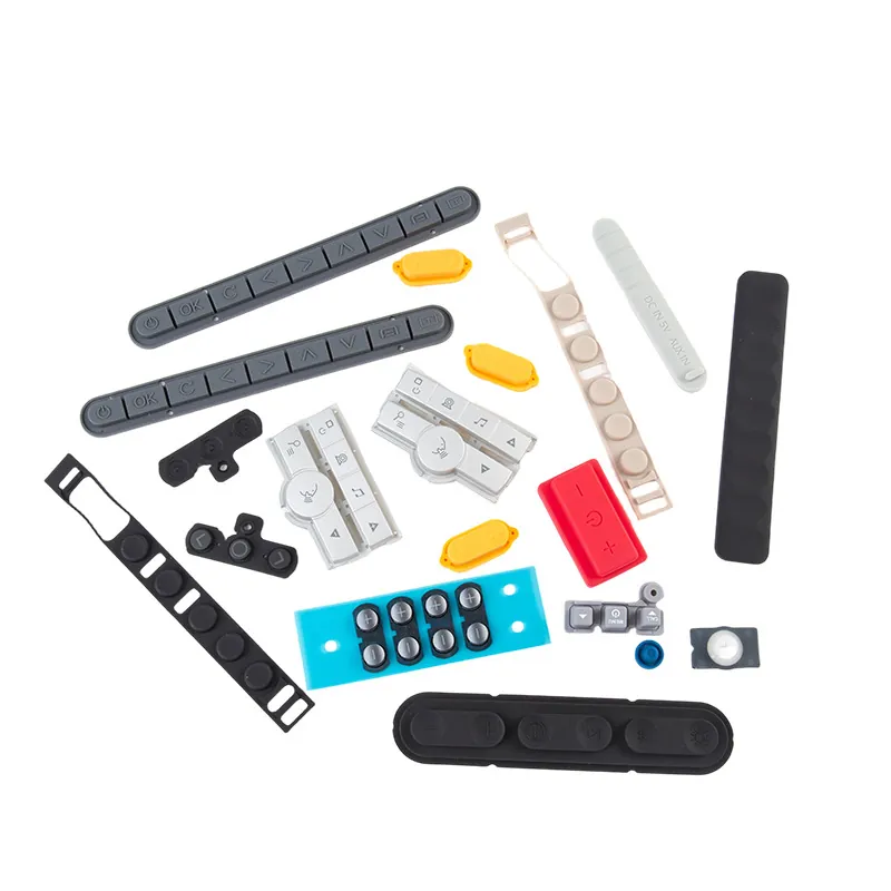
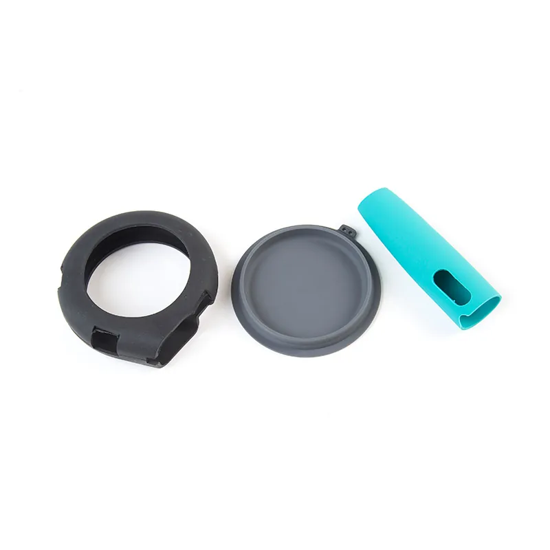
Most problems that appear at first article were designed in months earlier. DFM review exists to find them on the drawing, where a change costs nothing, rather than in the tool, where it does. This guide covers the rules that actually change outcomes.
Section Thickness
Uneven wall thickness is the single most common cause of trouble in moulded elastomer. Thick sections cure more slowly than thin ones, so a part with both ends up with a thin region that is over-cured and brittle next to a thick region that is under-cured and dimensionally unstable. Where a design needs a thick feature, the usual fix is to core it out or to accept a slower cure and its cost, rather than to leave the wall uniform on paper and uneven in the tool.
Radii, Corners and Tear
Silicone tears at sharp internal corners. A sharp corner concentrates stress exactly where the part flexes, and the failure starts there. Adding an internal radius is usually the cheapest change available in the whole review, and it is the one most often missing. Avoid thin, sharp features on a sealing lip for the same reason.
Draft and Demoulding
- Vertical walls need draft, or the part drags on the tool and distorts as it comes out
- Soft compounds need more draft than hard ones, because they deform under their own weight when unsupported
- Deep, narrow features are difficult to fill and difficult to eject consistently
- Undercuts generally need a split or a collapsing core, which adds tooling cost and parting lines - sometimes it is better to redesign the feature away
Parting Lines and Flash in the Design
The parting line has to sit somewhere, and flash will form along it. The design question is whether that line lands on a sealing face or a visible surface. If it does, the fix belongs in the geometry: move the line, add a groove that puts the contact band away from it, or orient the part so the witness mark is hidden. What does not work is asking for invisible trimming.
The Defects a DFM Review Prevents
| Symptom | Usual design cause |
|---|---|
| Short fill in a thin or deep feature | Feature too thin or too far from the fill point |
| Tearing at demoulding | Sharp internal corner or insufficient draft |
| Bonding line that splits later | Flow fronts meeting in a thin web |
| Inconsistent hardness across the part | Uneven section thickness |
| Flash on a functional face | Parting line placed on the sealing band |
| Distortion after demoulding | Thin section unsupported by the geometry |
What Our Review Covers
- Section thickness and where it changes
- Internal and external radii against the flexing direction
- Draft on vertical walls
- Undercuts, and whether a split is justified
- Parting line position against cosmetic and sealing surfaces
- Whether the compound and hardness suit the geometry
- Whether the part should be a single moulding or an assembly
Frequently Asked Questions
Before the tool is cut, ideally while the design is still fluid. Changes on the drawing cost nothing; the same change after the tool exists means rework or a new tool.
Uneven section thickness, followed closely by sharp internal corners where the part flexes. Both lead to failures that look like material problems but are geometry problems.
They usually need a split or a collapsing core, which adds tooling cost and extra parting lines. If the feature is not doing real work, redesigning it away is often the cheaper route.
A 3D model is the best starting point - send STEP, IGES or STL. A 2D drawing with the critical dimensions marked is even more useful, and a sample or photograph helps where no CAD exists.
It may propose changes, but nothing is changed without your agreement. Where a change is needed to make the part manufacturable, we explain what it fixes and what it costs to leave alone.
Related Pages
Custom Silicone Parts
Parts developed from a drawing or a model, with manufacturability reviewed before quoting.
Silicone Components for Drones
Lightweight sealing and damping components where geometry drives the design.
Silicone Molding
Which process suits the geometry, and what that means for the design rules.
Request a Quote
Send the model or drawing and manufacturability feedback comes back before pricing.